Product Description
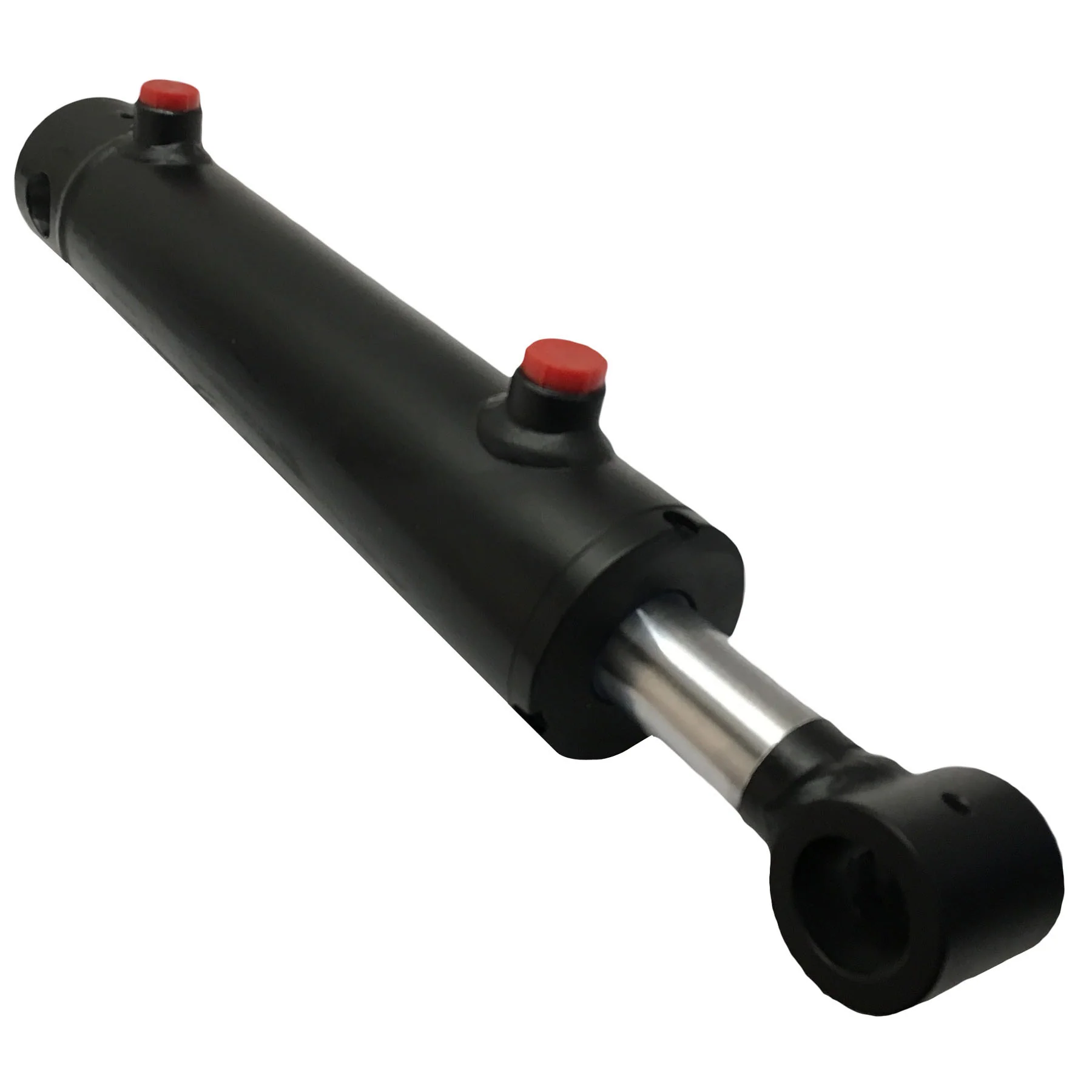
Hydraulic cylinders, mill type CDH
- Rexroth standard
- Series H1
- Component series 3X
- Nominal pressure 250 bar
- Piston Ø 40 … 320 mm
- Piston rod Ø 22 … 220 mm
- Stroke length up to 6000 m
-
Ordering code
01
02
03
04
05
06
07
08
09
10
11
12
13
14
15
16
CD
H1
/
/
/
A
3X
/
01
Single rod cylinder
CD
02
Series
H1
Types of mounting
03
Swivel eye at cylinder base
MP31)
Self-aligning clevis at cylinder base
MP5
Round flange at the cylinder head
MF3
Round flange at the cylinder base
MF4
Trunnion
MT42)
Foot mounting
MS2
04
Piston Ø (ØAL) 40 … 320 mm
…
05
Piston rod Ø (ØMM) 22 … 220 mm
…
06
Stroke length in mm3)
…
Design principle
07
Head and base flanged
A
08
Component series 30 … 39 (30 … 39: unchanged installation and connection dimensions)
3X
Line connection / version
09
According to ISO 1179-1 (pipe thread ISO 228-1)
B
According to ISO 9974-1 (metric thread ISO 261)
M
Flange connection according to ISO 6162-2 tab. 2 type 1 (≙ SAE 6000 PSI)
D4; 9)
Flange connection according to ISO 6164 tab. 2
H4)
according to ISO 1179-1 (pipe thread ISO 228-1) with flat pipe flange
C31)
For directional and high-response valves
Subplate NG6
P4; 5)
Subplate NG10
T4; 6)
Subplate NG16
U4; 7)
Subplate NG25
V4; 8)
For SL and SV valves
Subplate NG6
A4; 5; 15)
Subplate NG10
E4; 6; 15)
Subplate NG20
L4; 7; 15)
Subplate NG30
N4; 8; 15)
Line connection/position at cylinder head
10
View to piston rod30)
1
2
3
4
Line connection/position at cylinder base
11
View to piston rod30)
1
234)
3
434)
Piston rod design
12
Hard chromium-plated
C
Hardened and hard chromium-plated
H12)
Nickel-plated and hard chromium-plated
N19)
Piston rod end
13
Thread for swivel head CGAS
A
Thread for swivel head CGA, CGAK, plain clevis CSA
G13)
With mounted swivel head CGAS
S
With mounted swivel head CGA
L13)
With mounted swivel head CGAK
M13)
With mounted swivel head CSA
N1)
End position cushioning
14
Without end position cushioning
U
Both sides, self-adjusting
D1)
Both sides, adjustable
E
Seal design
15
For mineral oil HL, HLP and oil-in-water emulsion HFA
Standard seal system
M
Standard seal system with guide rings
L
Reduced friction
heavy industryR
For mineral oil HL, HLP, oil-in-water emulsion HFA and water glycol HFC
Standard seal system HFC
G
Servo quality/reduced friction
T
Chevron seal kits
A
For HDFR phosphate ester and HFDU polyol ester
Servo quality/reduced friction
S
Standard seal system FKM
V
Chevron seal kits
B
Option
16
Additional options, fill fields for additional options
Z
Without additional options, do not fill fields for additional options
W
Additional options
Fields for additional options
17
18
19
20
21
22
23
24
Z
17
Without inductive proximity switches
W
Inductive proximity switches without mating connector – separate order
E37)
18
Without additional guide rings
W
Additional guide rings
F10; 28)
19
Without measuring coupling
W
Measuring coupling, on both sides
A
20
Standard conical grease nipple, DIN 71412 Form A
W
Spherical bearing, maintenance-free
A 14; 35)
Flanged grease nipple, DIN 3404 Form A
B
21
Without piston rod extension
W
Piston rod extension “LY”, specify in mm in plain text
Y
22
Priming class CP3
W
Painting class CP4
B21)
Painting class CP5
L21)
Painting class CP6
U21)
Painting class CP7
E21)
23
Without oil filling
W
With oil filling
F
24
Without test certificate
W
With acceptance test certificate 3.1 based on EN 15714
C
1) Only piston Ø 40 … 200 mm 2) Trunnion position freely selectable. When ordering, always specify the “XV” dimensions in the plain text in mm 3) For max. available stroke length see Technical data and for admissible stroke length (according to the kinking calculation) see Project plHangZhou information. 4) Not possible with MF4 5) Piston Ø 40 … 80 mm, only position 11, subplates only possible in combination with line connection “B” at the head 6) Piston Ø 63 … 200 mm, only position 11, subplates only possible in combination with line connection “B” at the head 7) Piston Ø 125 … 200 mm, only position 11, subplates only possible in combination with line connection “B” at the head 8) Only piston Ø 160 … 200 mm, only position 11, subplates only possible in combination with line connection “B” at the head 9) Only piston Ø 80 … 320 mm 10) Seal designs A, B not possible; piston Ø 220 … 320 mm standard 12) Only piston rod Ø 22 … 140 mm 13) Not with piston Ø 320 mm 14) Not possible with piston rod end “N” 15) Subplates for SL and SV valves (isolator valves)
Please note: Seal designs T, G, L, R, S and V are not designed for the static holding function!19) Only piston rod Ø 45 … 160 mm 21) Specify RAL color in the plain text 28) With seal design “L” standard 30) All graphical representations in the data sheet show position 1 31) With MS2, only position 11 is possible 34) With MF4 and line connection B, M or C not possible 35) Not possible with MP3 37) Min. stroke length = 20 mm
Order example: CDH1MP5/100/56/300A3X/B11CADMW CDH1MP5/100/56/300A3X/B11CADMZ EWABWWWW
| Certification: | CE, ISO9001 |
|---|---|
| Pressure: | High Pressure |
| Work Temperature: | High Temperature |
| Customization: |
Available
|
|
|---|
.shipping-cost-tm .tm-status-off{background: none;padding:0;color: #1470cc}
|
Shipping Cost:
Estimated freight per unit. |
about shipping cost and estimated delivery time. |
|---|
| Payment Method: |
|
|---|---|
|
Initial Payment Full Payment |
| Currency: | US$ |
|---|
| Return&refunds: | You can apply for a refund up to 30 days after receipt of the products. |
|---|
Can double-acting hydraulic cylinders be employed in material handling equipment for pushing and pulling?
Yes, double-acting hydraulic cylinders are commonly employed in material handling equipment for pushing and pulling tasks. Here’s a detailed explanation:
1. Pushing Function: Double-acting hydraulic cylinders can generate significant pushing force, making them well-suited for material handling equipment that requires pushing capabilities. By supplying pressurized hydraulic fluid to one side of the cylinder, the piston extends, exerting force in the desired direction. This force can be utilized to push heavy objects, such as crates, pallets, or machinery components. The ability to generate substantial pushing force allows material handling equipment to move or position loads efficiently.
2. Pulling Function: In addition to pushing, double-acting hydraulic cylinders can also be employed for pulling tasks in material handling equipment. By supplying fluid to the opposite side of the cylinder, the piston retracts, creating a pulling force. This pulling force enables the equipment to tow or drag objects, such as trailers or carts, facilitating material transport within a facility or across a worksite.
3. Bi-Directional Force Generation: The bi-directional operation of double-acting hydraulic cylinders is advantageous for both pushing and pulling applications. By utilizing both the extension and retraction strokes, material handling equipment can generate force in both directions, enhancing versatility and productivity. The ability to generate force in multiple directions allows for efficient maneuvering, positioning, and handling of various loads, contributing to the overall effectiveness of the material handling process.
4. Control and Precision: Double-acting hydraulic cylinders provide precise control over the pushing and pulling forces exerted by material handling equipment. The hydraulic system can be designed with valves, control systems, and pressure regulation mechanisms to adjust and fine-tune the force output. This level of control enables operators to apply the necessary force with precision, preventing damage to the handled materials or equipment. The ability to control and modulate the force also ensures the safety of operators and enhances the overall efficiency of material handling operations.
5. Adaptability and Customization: Double-acting hydraulic cylinders can be adapted and customized to meet the specific requirements of material handling equipment. They can be designed with different stroke lengths, bore sizes, and mounting configurations to fit the equipment’s structure and hydraulic system. This adaptability allows for seamless integration of the hydraulic cylinders into the material handling equipment, optimizing performance, and ensuring efficient pushing and pulling operations.
Given their capability for pushing and pulling functions, bi-directional force generation, control and precision, as well as adaptability and customization, double-acting hydraulic cylinders are widely employed in material handling equipment for efficient and effective pushing and pulling tasks.
How does a double-acting hydraulic cylinder contribute to precise force application?
A double-acting hydraulic cylinder plays a crucial role in enabling precise force application. Here’s a detailed explanation:
1. Control over Force Generation: Double-acting hydraulic cylinders provide precise control over the force they generate. By supplying pressurized hydraulic fluid to one side of the cylinder, the piston extends, exerting force in a specific direction. By supplying fluid to the other side, the piston retracts, creating an opposite force. The hydraulic system can be designed with valves, control systems, and pressure regulation mechanisms to adjust and fine-tune the force output. This level of control allows operators to apply the necessary force with precision, whether it’s for lifting, pushing, pulling, or any other task.
2. Adjustable Pressure: The hydraulic system powering the double-acting cylinder allows for adjustable pressure settings. By regulating the hydraulic pressure, operators can precisely control the force output of the cylinder. This adjustability is especially useful when handling delicate or sensitive materials that require a specific amount of force to avoid damage. By fine-tuning the pressure, operators can ensure that the force applied is precisely tailored to the requirements of the task at hand.
3. Smooth and Gradual Force Application: Double-acting hydraulic cylinders facilitate smooth and gradual force application. The hydraulic fluid in the system is incompressible, which means that force is distributed evenly throughout the system. As the hydraulic fluid is pressurized, the force is transmitted to the piston, resulting in a smooth and controlled movement. This allows for gentle and gradual force application, minimizing the risk of sudden or jarring movements that could damage the equipment or the materials being handled.
4. Position and Stroke Control: Double-acting hydraulic cylinders provide precise control over the position and stroke of the piston. The hydraulic fluid can be regulated to stop the piston at specific positions, allowing for precise positioning of loads or equipment. Additionally, the stroke length of the cylinder can be adjusted to control the range of motion. This level of control over position and stroke enables operators to apply force with precision, ensuring accurate and repeatable results in various applications.
5. Feedback and Monitoring: Advanced hydraulic systems can incorporate feedback mechanisms and sensors to monitor and provide real-time information about the force being applied by the double-acting hydraulic cylinder. This feedback allows operators to monitor the force levels, make adjustments if necessary, and ensure that the desired force is being accurately applied. By having access to this information, operators can maintain precise control over force application throughout the operation.
Overall, through control over force generation, adjustable pressure settings, smooth and gradual force application, position and stroke control, as well as feedback and monitoring capabilities, double-acting hydraulic cylinders contribute significantly to precise force application. Their ability to provide controlled and tailored force output makes them essential components in applications where accuracy and precision are paramount.
How does a double-acting hydraulic cylinder handle variations in hydraulic pressure?
A double-acting hydraulic cylinder is designed to handle variations in hydraulic pressure while maintaining its functionality and performance. Here’s a detailed explanation:
1. Balanced Design: Double-acting hydraulic cylinders are designed with a balanced piston and rod arrangement. This design ensures that the hydraulic pressure acts equally on both sides of the piston, allowing for consistent and balanced force generation. As a result, the cylinder can handle variations in hydraulic pressure without compromising its ability to extend and retract smoothly.
2. Efficient Sealing System: Double-acting cylinders incorporate a sealing system that helps maintain the integrity of the hydraulic fluid and prevents leakage. The piston and rod seals, typically made of materials like rubber or polyurethane, create a tight seal between the piston and the cylinder barrel. This sealing system ensures that hydraulic pressure is effectively contained within the cylinder, reducing the impact of pressure variations on the cylinder’s performance.
3. Pressure Relief Mechanism: In situations where there are significant variations in hydraulic pressure, double-acting hydraulic cylinders may incorporate a pressure relief mechanism. This mechanism allows excess pressure to be released from the cylinder, preventing damage to the seals and other internal components. Pressure relief valves or adjustable relief valves are commonly used to regulate the pressure within the cylinder and protect it from excessive pressure fluctuations.
4. Robust Construction: Double-acting hydraulic cylinders are constructed using high-strength materials such as steel or aluminum. This robust construction enables the cylinder to withstand variations in hydraulic pressure without deformations or failures. The materials used, along with proper engineering and manufacturing techniques, ensure the structural integrity of the cylinder even under challenging pressure conditions.
5. Performance Testing and Quality Control: Manufacturers of double-acting hydraulic cylinders subject their products to rigorous performance testing and quality control measures. These tests evaluate the cylinder’s ability to handle variations in hydraulic pressure, ensuring that it meets the required performance and safety standards. Through these quality control processes, any potential issues related to pressure variations are identified and addressed before the cylinder is deployed.
By employing a balanced design, efficient sealing system, pressure relief mechanisms, robust construction, and thorough quality control, double-acting hydraulic cylinders can effectively handle variations in hydraulic pressure. These features ensure the cylinder’s reliability, longevity, and consistent performance in diverse hydraulic systems and applications.


editor by CX 2023-12-13