Product Description
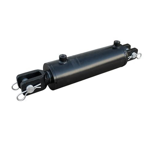
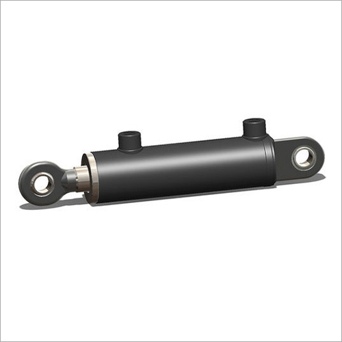
Hydraulic cylinders, mill type CDH
- Rexroth standard
- Series H1
- Component series 3X
- Nominal pressure 250 bar
- Piston Ø 40 … 320 mm
- Piston rod Ø 22 … 220 mm
- Stroke length up to 6000 m
-
Ordering code
01
02
03
04
05
06
07
08
09
10
11
12
13
14
15
16
CD
H1
/
/
/
A
3X
/
01
Single rod cylinder
CD
02
Series
H1
Types of mounting
03
Swivel eye at cylinder base
MP31)
Self-aligning clevis at cylinder base
MP5
Round flange at the cylinder head
MF3
Round flange at the cylinder base
MF4
Trunnion
MT42)
Foot mounting
MS2
04
Piston Ø (ØAL) 40 … 320 mm
…
05
Piston rod Ø (ØMM) 22 … 220 mm
…
06
Stroke length in mm3)
…
Design principle
07
Head and base flanged
A
08
Component series 30 … 39 (30 … 39: unchanged installation and connection dimensions)
3X
Line connection / version
09
According to ISO 1179-1 (pipe thread ISO 228-1)
B
According to ISO 9974-1 (metric thread ISO 261)
M
Flange connection according to ISO 6162-2 tab. 2 type 1 (≙ SAE 6000 PSI)
D4; 9)
Flange connection according to ISO 6164 tab. 2
H4)
according to ISO 1179-1 (pipe thread ISO 228-1) with flat pipe flange
C31)
For directional and high-response valves
Subplate NG6
P4; 5)
Subplate NG10
T4; 6)
Subplate NG16
U4; 7)
Subplate NG25
V4; 8)
For SL and SV valves
Subplate NG6
A4; 5; 15)
Subplate NG10
E4; 6; 15)
Subplate NG20
L4; 7; 15)
Subplate NG30
N4; 8; 15)
Line connection/position at cylinder head
10
View to piston rod30)
1
2
3
4
Line connection/position at cylinder base
11
View to piston rod30)
1
234)
3
434)
Piston rod design
12
Hard chromium-plated
C
Hardened and hard chromium-plated
H12)
Nickel-plated and hard chromium-plated
N19)
Piston rod end
13
Thread for swivel head CGAS
A
Thread for swivel head CGA, CGAK, plain clevis CSA
G13)
With mounted swivel head CGAS
S
With mounted swivel head CGA
L13)
With mounted swivel head CGAK
M13)
With mounted swivel head CSA
N1)
End position cushioning
14
Without end position cushioning
U
Both sides, self-adjusting
D1)
Both sides, adjustable
E
Seal design
15
For mineral oil HL, HLP and oil-in-water emulsion HFA
Standard seal system
M
Standard seal system with guide rings
L
Reduced friction
heavy industryR
For mineral oil HL, HLP, oil-in-water emulsion HFA and water glycol HFC
Standard seal system HFC
G
Servo quality/reduced friction
T
Chevron seal kits
A
For HDFR phosphate ester and HFDU polyol ester
Servo quality/reduced friction
S
Standard seal system FKM
V
Chevron seal kits
B
Option
16
Additional options, fill fields for additional options
Z
Without additional options, do not fill fields for additional options
W
Additional options
Fields for additional options
17
18
19
20
21
22
23
24
Z
17
Without inductive proximity switches
W
Inductive proximity switches without mating connector – separate order
E37)
18
Without additional guide rings
W
Additional guide rings
F10; 28)
19
Without measuring coupling
W
Measuring coupling, on both sides
A
20
Standard conical grease nipple, DIN 71412 Form A
W
Spherical bearing, maintenance-free
A 14; 35)
Flanged grease nipple, DIN 3404 Form A
B
21
Without piston rod extension
W
Piston rod extension “LY”, specify in mm in plain text
Y
22
Priming class CP3
W
Painting class CP4
B21)
Painting class CP5
L21)
Painting class CP6
U21)
Painting class CP7
E21)
23
Without oil filling
W
With oil filling
F
24
Without test certificate
W
With acceptance test certificate 3.1 based on EN 15714
C
1) Only piston Ø 40 … 200 mm 2) Trunnion position freely selectable. When ordering, always specify the “XV” dimensions in the plain text in mm 3) For max. available stroke length see Technical data and for admissible stroke length (according to the kinking calculation) see Project plHangZhou information. 4) Not possible with MF4 5) Piston Ø 40 … 80 mm, only position 11, subplates only possible in combination with line connection “B” at the head 6) Piston Ø 63 … 200 mm, only position 11, subplates only possible in combination with line connection “B” at the head 7) Piston Ø 125 … 200 mm, only position 11, subplates only possible in combination with line connection “B” at the head 8) Only piston Ø 160 … 200 mm, only position 11, subplates only possible in combination with line connection “B” at the head 9) Only piston Ø 80 … 320 mm 10) Seal designs A, B not possible; piston Ø 220 … 320 mm standard 12) Only piston rod Ø 22 … 140 mm 13) Not with piston Ø 320 mm 14) Not possible with piston rod end “N” 15) Subplates for SL and SV valves (isolator valves)
Please note: Seal designs T, G, L, R, S and V are not designed for the static holding function!19) Only piston rod Ø 45 … 160 mm 21) Specify RAL color in the plain text 28) With seal design “L” standard 30) All graphical representations in the data sheet show position 1 31) With MS2, only position 11 is possible 34) With MF4 and line connection B, M or C not possible 35) Not possible with MP3 37) Min. stroke length = 20 mm
Order example: CDH1MP5/100/56/300A3X/B11CADMW CDH1MP5/100/56/300A3X/B11CADMZ EWABWWWW
| Certification: | CE, ISO9001 |
|---|---|
| Pressure: | High Pressure |
| Work Temperature: | High Temperature |
| Customization: |
Available
|
|
|---|
.shipping-cost-tm .tm-status-off{background: none;padding:0;color: #1470cc}
|
Shipping Cost:
Estimated freight per unit. |
about shipping cost and estimated delivery time. |
|---|
| Payment Method: |
|
|---|---|
|
Initial Payment Full Payment |
| Currency: | US$ |
|---|
| Return&refunds: | You can apply for a refund up to 30 days after receipt of the products. |
|---|
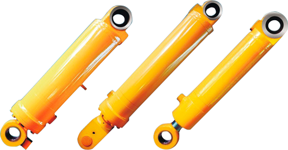
Can double-acting hydraulic cylinders be used in construction equipment like backhoes?
Yes, double-acting hydraulic cylinders are commonly used in construction equipment like backhoes. Here’s a detailed explanation:
1. Lifting and Digging Functions: Backhoes are versatile construction machines used for various tasks, including digging, trenching, lifting, and material handling. Double-acting hydraulic cylinders play a crucial role in enabling the lifting and digging functions of a backhoe. These cylinders are typically used to control the movement of the boom, dipper stick, and bucket assembly. By extending and retracting the hydraulic cylinders, the boom can be raised, lowered, and positioned precisely, allowing for efficient digging and material handling operations.
2. Bi-Directional Force Generation: Double-acting hydraulic cylinders are well-suited for the requirements of backhoes due to their ability to generate force in both directions. This bi-directional operation is essential for the backhoe’s lifting and digging functions. By supplying pressurized hydraulic fluid to one side of the cylinder, the piston extends, producing force that raises or extends the boom. Conversely, supplying fluid to the other side of the cylinder retracts the piston, allowing for the lowering or retraction of the boom. This bi-directional force generation enables precise control over the movement and positioning of the backhoe’s working components.
3. Precise Control and Positioning: Backhoes often require precise control and positioning of the boom, dipper stick, and bucket assembly. Double-acting hydraulic cylinders contribute to this precise control by allowing operators to adjust the speed and force of the cylinder’s movement. By regulating the hydraulic pressure and flow rate, the operator can control the speed and smoothness of the cylinder’s extension and retraction. This level of control enables accurate and controlled movement, facilitating precise digging, lifting, and material handling tasks.
4. Adaptability and Customization: Double-acting hydraulic cylinders can be customized to meet the specific requirements of backhoes and other construction equipment. They can be designed with various stroke lengths, bore sizes, and mounting configurations to fit the backhoe’s hydraulic system and geometry. This adaptability ensures that the hydraulic cylinders integrate seamlessly with the backhoe’s structure and hydraulic circuit, optimizing performance and efficiency.
5. Durability and Reliability: Construction equipment like backhoes operate in demanding and often harsh conditions. Double-acting hydraulic cylinders are built to withstand these challenging environments. They are constructed from robust materials, such as high-strength steel, and equipped with reliable sealing mechanisms to prevent the ingress of contaminants. This ensures the durability and reliability of the hydraulic cylinders, allowing them to withstand the rigors of construction sites and provide consistent performance over time.
Given their suitability for lifting and digging functions, bi-directional force generation, precise control and positioning, adaptability and customization, as well as durability and reliability, double-acting hydraulic cylinders are extensively used in construction equipment like backhoes.
How does a double-acting hydraulic cylinder contribute to precise force application?
A double-acting hydraulic cylinder plays a crucial role in enabling precise force application. Here’s a detailed explanation:
1. Control over Force Generation: Double-acting hydraulic cylinders provide precise control over the force they generate. By supplying pressurized hydraulic fluid to one side of the cylinder, the piston extends, exerting force in a specific direction. By supplying fluid to the other side, the piston retracts, creating an opposite force. The hydraulic system can be designed with valves, control systems, and pressure regulation mechanisms to adjust and fine-tune the force output. This level of control allows operators to apply the necessary force with precision, whether it’s for lifting, pushing, pulling, or any other task.
2. Adjustable Pressure: The hydraulic system powering the double-acting cylinder allows for adjustable pressure settings. By regulating the hydraulic pressure, operators can precisely control the force output of the cylinder. This adjustability is especially useful when handling delicate or sensitive materials that require a specific amount of force to avoid damage. By fine-tuning the pressure, operators can ensure that the force applied is precisely tailored to the requirements of the task at hand.
3. Smooth and Gradual Force Application: Double-acting hydraulic cylinders facilitate smooth and gradual force application. The hydraulic fluid in the system is incompressible, which means that force is distributed evenly throughout the system. As the hydraulic fluid is pressurized, the force is transmitted to the piston, resulting in a smooth and controlled movement. This allows for gentle and gradual force application, minimizing the risk of sudden or jarring movements that could damage the equipment or the materials being handled.
4. Position and Stroke Control: Double-acting hydraulic cylinders provide precise control over the position and stroke of the piston. The hydraulic fluid can be regulated to stop the piston at specific positions, allowing for precise positioning of loads or equipment. Additionally, the stroke length of the cylinder can be adjusted to control the range of motion. This level of control over position and stroke enables operators to apply force with precision, ensuring accurate and repeatable results in various applications.
5. Feedback and Monitoring: Advanced hydraulic systems can incorporate feedback mechanisms and sensors to monitor and provide real-time information about the force being applied by the double-acting hydraulic cylinder. This feedback allows operators to monitor the force levels, make adjustments if necessary, and ensure that the desired force is being accurately applied. By having access to this information, operators can maintain precise control over force application throughout the operation.
Overall, through control over force generation, adjustable pressure settings, smooth and gradual force application, position and stroke control, as well as feedback and monitoring capabilities, double-acting hydraulic cylinders contribute significantly to precise force application. Their ability to provide controlled and tailored force output makes them essential components in applications where accuracy and precision are paramount.
What are the key components and design features of a double-acting hydraulic cylinder?
A double-acting hydraulic cylinder consists of several key components and incorporates specific design features to enable its functionality. Here’s a detailed explanation:
1. Barrel: The barrel, also known as the cylinder tube, is a cylindrical structure that provides the main body of the hydraulic cylinder. It is typically constructed from high-strength, durable materials such as steel or aluminum to withstand the hydraulic pressure and external forces.
2. Piston: The piston is a cylindrical component that divides the interior of the hydraulic cylinder into two chambers—the cap-end chamber and the rod-end chamber. It is usually made of materials like steel or cast iron. The piston is designed to fit tightly within the barrel, forming a seal to prevent hydraulic fluid leakage between the chambers.
3. Rod: The rod, also known as the piston rod or plunger, is connected to the piston and extends through one end of the hydraulic cylinder. It provides the external connection point for attaching loads or other mechanical components. The rod is typically made of high-strength steel to withstand the forces applied during operation.
4. Seals: Seals are essential components in double-acting hydraulic cylinders to maintain the separation of the two chambers and prevent hydraulic fluid leakage. There are various types of seals used, including piston seals, rod seals, and wiper seals. These seals are typically made of materials such as rubber or polyurethane and are designed to provide an effective barrier against fluid leakage.
5. Hydraulic Ports: A double-acting hydraulic cylinder has two hydraulic ports—one connected to the cap end and the other connected to the rod end of the cylinder. These ports enable the inflow and outflow of hydraulic fluid to and from the respective chambers. The hydraulic ports are typically equipped with fittings or connectors to facilitate the connection of hydraulic hoses or pipes.
6. Mounting Options: Double-acting hydraulic cylinders are designed with various mounting options to facilitate their installation and integration into hydraulic systems. Common mounting options include flange mounts, trunnion mounts, clevis mounts, and foot mounts. These mounting options provide flexibility in connecting the hydraulic cylinder to other components or structures.
7. Cushioning Mechanism: Some double-acting hydraulic cylinders incorporate cushioning mechanisms to dampen the impact and decelerate the piston at the end of its stroke. This helps to reduce shock, minimize noise, and prolong the lifespan of the cylinder. Cushioning mechanisms can include adjustable cushions, fixed cushions, or hydraulic cushioning systems.
8. Surface Coatings: Depending on the application and operating conditions, double-acting hydraulic cylinders may feature surface coatings to enhance their performance and durability. Common surface coatings include chrome plating or other corrosion-resistant coatings to protect against wear, corrosion, and environmental factors.
These key components and design features work together to enable the functionality and reliability of double-acting hydraulic cylinders. They allow for the controlled extension and retraction of the piston, the generation of bidirectional force, and the efficient transmission of hydraulic power.


editor by CX 2023-11-30